SOA and RSOA
Laser Diodes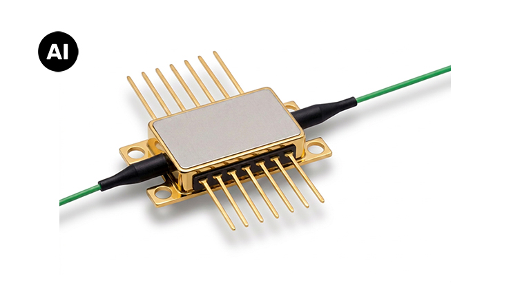
Semiconductor-based optical amplifiers for high-performance photonic systems: SOA and RSOA
Semiconductor Optical Amplifiers (SOA) and Reflective Semiconductor Optical Amplifiers (RSOA) amplify optical signals directly within a semiconductor gain medium. These compact, electrically driven devices are widely used in telecommunications, LiDAR, free-space optical communication, network measurement systems, and External Cavity Lasers (ECLs). Depending on the application and system architecture, solutions are available for both the O-band around 1310 nm and the C-band around 1550 nm.
Compact and Efficient Optical Signal Amplification
An SOA amplifies an incoming optical signal by guiding it through an electrically pumped active semiconductor region. Within this gain medium, stimulated emission generates additional photons at the same wavelength and phase, resulting in signal amplification at the output. Compared to fiber amplifiers, SOAs offer a significantly smaller footprint and can be readily integrated into photonic circuits and optical subsystems.
RSOAs operate on the same amplification principle but feature a highly reflective facet at one end of the device. The optical signal passes through the active region twice before being reflected back toward the input side. This architecture combines optical gain and reflection within a single component, enabling highly compact gain-chip and modulation concepts.
SOA or RSOA: Which Solution Is Right for Your Application?
SOAs are the preferred choice when optical signals need to be amplified in a through-path configuration, for example as booster amplifiers, pre-amplifiers, or inline amplifiers. RSOAs are particularly suitable for applications requiring reflective signal propagation or when the device serves as a gain chip within an external laser cavity. Key selection criteria include operating wavelength, gain requirements, output power, saturation characteristics, polarization dependence, package format, and thermal management considerations.
Wavelength Ranges and Package Options
For telecommunications and sensing applications, the most common operating wavelength ranges are the O-band around 1310 nm and the C-band around 1550 nm. Depending on the level of integration required, RSOAs are available as bare dies, chip-on-carriers, high-power versions, multi-channel arrays, or fully packaged devices in industry-standard butterfly packages. Customization of optical and electrical characteristics can be provided based on specific project requirements and application needs.
Find the right SOA or RSOA for your application:
| Designation | Wavelength | SOA or RSOA | Optical Power | Housing |
|---|---|---|---|---|
| 1280 nm | SOA | 24.9 dBM | Butterfly | |
| 1280 nm | SOA | 0,45 W | Chip on Carrier | |
| 1280 nm | SOA | 0.45 W | Chip | |
| 1280 nm | SOA | 70 mW | Chip | |
| 1310 nm | SOA | 17 dBM | Butterfly | |
| 1310 nm | SOA | 24.9 dBM | Butterfly | |
| 1310 nm | RSOA | 0.2 W | Chip on Carrier | |
| 1310 nm | RSOA | 0.2 W | Chip on Carrier | |
| 1310 nm | SOA | 0.45 W | Chip on Carrier | |
| 1310 nm | SOA | 0.45 W | Chip on Carrier | |
| 1310 nm | RSOA | 6 mW | Chip on Carrier | |
| 1310 nm | RSOA | 0.2 W | Chip | |
| 1310 nm | SOA | 0.2 W | Chip | |
| 1310 nm | RSOA | 0.2 W | Chip | |
| 1310 nm | SOA | 0.45 W | Chip | |
| 1310 nm | SOA | 17 dBM | Chip | |
| 1311 nm | SOA | 17 dBM | Butterfly | |
| 1311 nm | RSOA | 6 mW | Chip | |
| 1520 nm | SOA | 24 dBM | Butterfly | |
| 1520 nm | RSOA | 0.375 W | Chip on Carrier | |
| 1520 nm | SOA | 0.39 W | Chip | |
| 1520 nm | RSOA | 70 mW | Chip | |
| 1550 nm | SOA | 17 dBM | Butterfly | |
| 1550 nm | RSOA | 23.5 dBM | Butterfly | |
| 1550 nm | SOA | 23.5 dBM | Butterfly | |
| 1550 nm | SOA | 24 dBM | Butterfly | |
| 1550 nm | RSOA | 0.2 W | Chip on Carrier | |
| 1550 nm | SOA | 0.35 W | Chip on Carrier | |
| 1550 nm | SOA | 0.375 W | Chip on Carrier | |
| 1550 nm | SOA | 0.375 W | Chip on Carrier | |
| 1550 nm | RSOA | 6 mW | Chip on Carrier | |
| 1550 nm | RSOA | 0.2 W | Chip | |
| 1550 nm | RSOA | 0.2 W | Chip | |
| 1550 nm | SOA | 0.35 W | Chip | |
| 1550 nm | SOA | 0.39 W | Chip | |
| 1550 nm | SOA | 70 mW | Chip | |
| 1551 nm | SOA | 17 dBM | Butterfly | |
| 1551 nm | RSOA | 0.2 W | Chip on Carrier | |
| 1551 nm | RSOA | 6 mW | Chip | |
| 1595 nm | SOA | 23 dBM | Butterfly | |
| 1595 nm | SOA | 23 dBM | Butterfly | |
| 1595 nm | SOA | 0.375 W | Chip on Carrier | |
| 1595 nm | SOA | 0.39 W | Chip |
Frequently Asked Questions (FAQs) About SOA and RSOA
An SOA is a semiconductor-based, electrically pumped optical amplifier. It amplifies an input signal as it passes through the active region and can also be used for optical signal processing.
In an SOA, the amplified light exits from the opposite side. In an RSOA, a highly reflective facet reflects the light back, so that the input and output are on the same side. This makes the RSOA particularly suitable as a gain element in external-cavity lasers.
Typical solutions operate in the O-band around 1310 nm and in the C-band around 1550 nm. Other wavelengths in the near-infrared range are possible depending on the device, semiconductor material, and application.
Depending on the product, bare dies, chip-on-carrier versions, single- or multi-channel arrays, and solutions housed in butterfly packages are available. The appropriate package type depends on coupling, heat dissipation, space requirements, and the integration process.
Typical applications include external cavity lasers (ECL), optical communications, LiDAR, free-space communications, and network measurement technology. In WDM-PON designs, RSOAs can also serve as flexible, so-called “colorless” transmitter components.
Key criteria include center wavelength and spectral operating range, small-signal gain, saturation output power, maximum output power, polarization dependence, current consumption, thermal requirements, and package type.
Yes. Depending on the quantity and technical requirements, the chip design, wavelength range, and optical and electrical characteristics can be tailored to the specific project. Please contact us for technical selection assistance.
A PERSONAL CONVERSATION Feel free to call us or send us an email via the following link Kontakt